For the BMW 3 E90, E91, E92, E93 2005, 2006, 2007, 2008, 2009, 2010, 2011, 2012 model year.
316d, 316i, 318d, 318i, 320si, 320d, 320i, 323i, 325d, 325i, 328i, 330d, 330i, 335d, 335i, Xi.
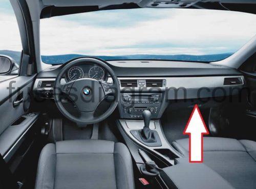
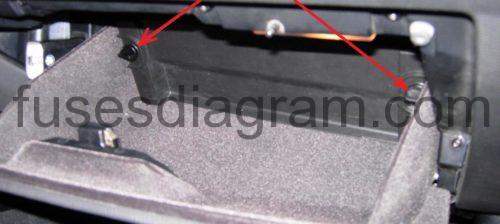
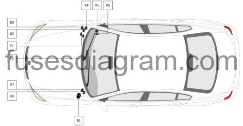
Locate fuse box.
Rotate both thumbscrews 90 degrees to unlock and remove cover plate.
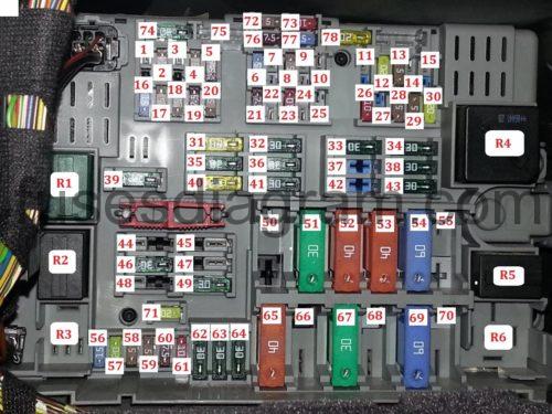
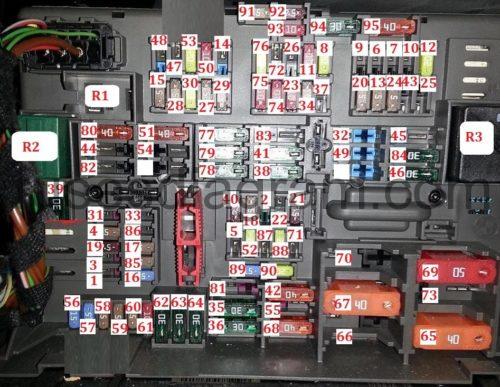
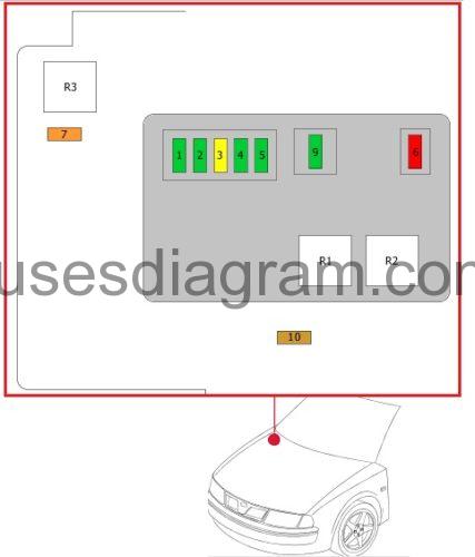
Fuse box diagram BMW E90 (type 1).
idintifying.
or
Legend.
| R1 | Windscreen wiper motor relay |
| R2 | Heated rear window relay |
| R3 | Rear screen wiper relay |
| R4 | Terminal 30 relay |
| R5 | Headlamp washer pump relay |
| R6 | Secondary air injection (AIR) pump relay |
| R7 | Horn relay |
| R8 | Fuel pump relay |
| R9 | Terminal 15 relay |
| F1 | (15A) ^08/05: Transmission control module (TCM) |
| F2 | (5A)Aerial selection control module |
| F3 | – |
| F4 | (5A) Ignition switch control module |
| F5 | (7,5A) Sunroof control |
| F6 | (15A) Transmission control module (TCM) |
| F7 | (20A) Auxiliary heater control module |
| F8 | (5A) CD changer |
| F9 | (10A) Cruise control distance range control module |
| F10 | (15A) Tow bar retract control module |
| F11 | (10A) Audio unit |
| F12 | (20A/15) Sunroof control or sequential gearbox |
| F13 | (5A) Controller area network (CAN) |
| F14 | – |
| F15 | – |
| F16 | (15A) Horns |
| F17 | – |
| F18 | (5A) CD changer |
| F19 | (7,5A) Siren |
| F20 | (5A) Dynamic stability control (DSC) |
| F21 | (7,5A) Mirror, passenger's side |
| F22 | (10A) Cruise control distance range control module |
| F23 | (10A) Video system |
| F24 | (5A) Tyre pressure monitor control module |
| F25 | (10A) |
| F26 | (10A)Telematics |
| F27 | (5A) Telephone |
| F28 | (5A) Parking distance control |
| F29 | (5A) Front heated seats |
| F30 | (20A) bmw e90 cigarette lighter fuse Rear 12V socket |
| F31 | (30A) ^08/05:ABSsystem Dynamic stability control (DSC) |
| F32 | (30A) Front left seat |
| F33 | (30A) Electric front seats |
| F34 | (30A) Audio unit output amplifier |
| F35 | (20A) ^08/05 Engine management |
| F36 | (30A) Fuel pump |
| F37 | (30A) Electric front seats |
| F38 | (30A) Transfer box control unit |
| F39 | (30A) Windscreen wipers |
| F40 | (20A) Radio |
| F41 | (30A) Footwell control unit |
| F42 | (30A) Driver's seat adjustment |
| F43 | (30A) Head lamp washers |
| F44 | (30A)Trailer control module |
| F45 | (20A) Trailer connector socket |
| F46 | (30A) Heated rear window |
| F47 | (20A) Trailer connector socket |
| F48 | – |
| F49 | (30A) Heated front seats |
| F50 | (40A) |
| F51 | (50A) Ignition switch control module |
| F52 | (50A) Footwell control unit |
| F53 | (50A) Footwell control unit |
| F54 | (60A) Engine management |
| F55 | – |
| F56 | (15A) Central locking system |
| F57 | (15A) Central locking system |
| F58 | (5A) Diagnostic connector |
| F59 | (5A) Steering column function control module |
| F60 | (7,5A) AC control module |
| F61 | (10A) Luggage compartment light(s) |
| F62 | (30A) Rear electric windows |
| F63 | (30A) |
| F64 | (30A) Rear electric windows |
| F65 | (40A) ABS system |
| F66 | (50A) Fuel heater |
| F67 | (50A) AC/heater blower control module |
| F68 | – |
| F69 | (50A) Engine coolant blower motor |
| F70 | – |
| F71 | Spare |
| F72 | Spare |
| F73 | Spare |
| F74 | Spare |
| F75 | Spare |
| F76 | Spare |
| F77 | Spare |
| F78 | Spare |
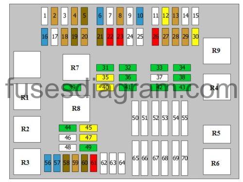
Fuse box diagram BMW E90 (type 2).
legend.
| 1 | Rear screen wiper relay |
| 2 | Windscreen wiper motor relay |
| 3 | |
| F1 | (10A) Roll-over bar control module |
| F2 | (5A) |
| F3 | – |
| F4 | (5A) Ignition switch control module |
| F5 | (20A) Fuel pump(FP) |
| F6 | (15A)^08/07:Transmission control module (TCM) |
| F7 | (20A) Auxiliary heater control module |
| F8 | (20A) Audio unit output amplifier |
| F9 | (10A) Cruise control distance range control module |
| F10 | (15A) Tow bar retract control module |
| F11 | (10A)^08/07: Audio unit |
| F12 | (20A) |
| F13 | (5A) Tyre pressure monitor control module |
| F14 | – |
| F15 | (5A) AC Intake air purity sensor |
| F16 | (15A) ^08/07:Horns |
| F17 | (10A) |
| F18 | (5A) Aerie selection control module |
| F19 | (7,5A) Alarm system |
| F20 | (5A) |
| F21 | (7,5A) |
| F22 | (10A) Cruise control distance range control module |
| F23 | (10A) |
| F24 | (5A) Tyre pressure monitor control module |
| F25 | (10A) Seat belt presenter control module |
| F26 | (10A) Telematics |
| F27 | (5A) |
| F28 | (5A) |
| F29 | (5A) Seat heating |
| F30 | (20A) bmw e90 cigarette lighter fuse |
| F31 | (20A) Multimedia control module |
| F32 | (30A) Seat adjustment control module, left front |
| F33 | (5A) |
| F34 | (5A) CD changer |
| F35 | (30A) ABS system |
| F36 | (30A) |
| F37 | (10A) |
| F38 | (30A) |
| F39 | (30A) |
| F40 | (7,5A) |
| F41 | (30A) |
| F42 | (40A) |
| F43 | (30A) Head lamp washers |
| F44 | (30A) Trailer control module |
| F45 | (40A) |
| F46 | (30A) Heated rear window |
| F47 | (20A) Trailer socket |
| F48 | – |
| F49 | (30A)^08/07:Seat adjustmentcontrol module, right front |
| F50 | (10A) Engine control module (ECM) |
| F51 | (50A) Ignition switch control module |
| F52 | (20A) |
| F53 | (20A) |
| F54 | (30A) Trailer control module |
| F55 | – |
| F56 | (15A) Central locking system |
| F57 | (15A) Central locking system |
| F58 | (5A) |
| F59 | (5A) Steering column function control module |
| F60 | (7,5A) AC control module |
| F61 | (10A) |
| F62 | (30A) Rear electric windows |
| F63 | (30A) |
| F64 | (30A) Rear electric windows |
| F65 | (40A) ABS system |
| F66 | (50A) |
| F67 | (30A) AC/heater blower control module |
| F68 | (40A) |
| F69 | (50A) Engine coolant blower motor |
| F70 | – |
| F71 | (20A) Trailer socket |
| F72 | – |
| F73 | – |
| F74 | (10A) |
| F75 | (10A) |
| F76 | (20A/30A) |
| F77 | (30A) |
| F78 | (30A) |
| F79 | (30A) |
| F80 | – |
| F81 | (30A) Trailer control module |
| F82 | – |
| F83 | – |
| F84 | (30A) Head lamp washers |
| F85 | – |
| F86 | – |
| F87 | – |
| F88 | (20A) ^08/07 Engine management |
| F89 | Spare |
| F90 | Spare |
| F91 | Spare |
| F92 | Spare |
| F93 | Spare |
| F94 | Spare |
| F95 | Spare |
Fuse box diagram BMW E90 (type 2 since 2008).
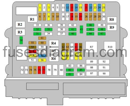
legend.
| Fuses | Amps | Circuits protected |
|---|---|---|
| 1 | 20A | Wash/wipe module |
| 2 | Not used | |
| 3 | 20A | Passenger's seat heater control unit |
| 4 | Not used | |
| 5 | Not used | |
| 6 | 5A | Fresh/recirculated air actuator DC-DC converter |
| 7 | 5A | Parking distance control Sliding roof |
| 8 | 20A | 12V socket |
| 9 | 5A | Telephone |
| 10 | 5A | Front heated seats |
| 11 | Not used | |
| 12 | 15A | Vacuum pump |
| 13 | 10A | Eject box |
| 14 | 15A | Radio |
| 15 | 20A | Amplifier |
| 16 | Not used | |
| 17 | Not used | |
| 18 | 10A | Video system |
| 19 | 5A | CD changer |
| 20 | 10A | Electric seats |
| 21 | 10A | Cruise control |
| 22 | 15A | Transmission |
| 23 | 20A | Additional air heater control unit |
| 24 | 15A | Trailer towing module |
| 25 | 20A | Roof |
| 26 | 5A | Dynamic stability control (DSC) Or Transfer box control unit Dynamic stability control (DSC) |
| 27 | 5A | Tyre pressure control unit |
| 28 | 5A | DC converter Cooling fan |
| 29 | 5A | Heated seats |
| 30 | Not used | |
| 31 | 30A | Trailer |
| 32 | 30A | Trailer control unit |
| 33 | 40A | Fuel heater |
| 34 | Not used | |
| 35 | 30A | Dynamic stability control (DSC) |
| 36 | 40A | Vehicle access control unit |
| 37 | Not used | |
| 38 | Not used | |
| 39 | Not used | |
| 40 | 30A | Transfer box control unit |
| 41 | 30A | Footwell control unit |
| 42 | 40A | Footwell control unit |
| 43 | 30A | Headlight washer module |
| 44 | 30A | Trailer control unit |
| 45 | 30A | Seat adjustment, right side |
| 46 | 30A | Seat adjustment, right side |
| 47 | 30A | Rear windscreen demister and defroster |
| 48 | 30A | Headlight washer |
| 49 | 40A | Steering |
| 50 | 30A | Wiper relay |
| 51 | 50A | Vehicle access control unit |
| 52 | 20A | Heated driver's seat |
| 53 | 10A | ARC |
| 54 | 7.5A | Alarm |
| 55 | 5A | Vehicle access control unit |
| 56 | 20A | Navigation |
| 57 | 15A | Horn |
| 58 | Not used | |
| 59 | Not used | |
| 60 | 5A | Multifunction display |
| 61 | 5A | Comfort access control unit Remote control receiver |
| 62 | 7.5A | Roof |
| 63 | 5A | Fresh/recirculated air actuator |
| 64 | Not used | |
| 65 | 10A | Transmission Dynamic drive |
| 66 | 7.5A | Mirror, passenger's side |
| 67 | 20A | Fuel pump relay |
| 68 | 20A | Heated driver's seat |
| 69 | 50A | Cooling fan (60A also used) |
| 70 | 20A | Fuel pump control relay |
| 71 | 20A | Trailer |
| 72 | Not used | |
| 73 | Not used | |
| 74 | 5A | Instrument cluster |
| 75 | 5A | Steering column |
| 76 | 10A | Multifunction display |
| 77 | 10A | Interior light(s) Air conditioning Luggage compartment light(s) |
| 78 | Not used | |
| 79 | Not used | |
| 80 | Not used | |
| 81 | 30A | Footwell control unit |
| 82 | 30A | Dynamic stability control (DSC) |
| 83 | Not used | |
| 84 | 40A | Footwell control unit |
| 85 | 30A | DC converter |
| 86 | 40A | Footwell control unit |
| 87 | Not used | |
| 88 | 40A | Blower |
| 89 | 40A | Secondary air injection pump |
| 90 | 40A | Dynamic stability control (DSC) |
| 91 | Not used | |
| 92 | 50A | Cooling fan |
| R1 | Rear wiper relay | |
| R2 | Wiper relay | |
| R3 | Wiper relay | |
| R4 | Terminal 15 relay Fuse and relay box in passenger compartment, fuses 6, 7, 9, 10, 30, relay R6 | |
| R5 | Fuel pump relay | |
| R6 | Horn relay | |
| R7 | Heated rear windscreen | |
| R8 | Terminal 30 relay Fuse and relay box in passenger compartment, fuses 13 – 15, 18 – 20, 22, 23, 25 – 28, 34, 45, 46, 49, 60, 70, 71, 76, 77 | |
| R9 | Junction box Fuse and relay box in passenger compartment, fuses 32, 56, 59, 61, 74 | |
| R10 | Not used |
Fuse box diagram BMW E90 (type 2 pre 2008).
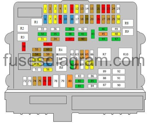
legend.
| Fuses | Amps | Circuits protected |
|---|---|---|
| 1 | 20A | Wash/wipe module |
| 2 | 5A | Instrument cluster Diagnostic connector |
| 3 | 20A | Passenger's seat heater control unit |
| 4 | 5A | Vehicle access control unit |
| 5 | 20A | Fuel pump relay |
| 6 | 15A | Transmission |
| 7 | 20A | Additional heater |
| 8 | 15A | Amplifier |
| 9 | 10A | Cruise control |
| 10 | 15A | Trailer towing module |
| 11 | 10A | Radio |
| 12 | 20A | Roof |
| 13 | 5A | Tyre pressure control unit |
| 14 | Not used | |
| 15 | 5A | Fresh/recirculated air actuator |
| 16 | 15 | Horn |
| 17 | Not used | |
| 18 | 5A | Fresh/recirculated air actuator |
| 19 | 7.5A | Alarm |
| 20 | 5A | Dynamic stability control (DSC) Or Transfer box control unit Dynamic stability control (DSC) |
| 21 | 7.5A | Mirror, passenger's side |
| 22 | 10A | Dynamic drive |
| 23 | 10A | Video system |
| 24 | 5A | DC converter Cooling fan |
| 25 | Not used | |
| 26 | 10A | Eject box |
| 27 | 10A | Telephone |
| 28 | 5A | Parking distance control Sliding roof |
| 29 | 5A | Front heated seats |
| 30 | 20A | 12V socket |
| 31 | 20A | Navigation |
| 32 | 30A | Seat adjustment, left side |
| 33 | 40A | Comfort access control unit |
| 34 | 5A | CD changer Or Fresh/recirculated air actuator |
| 35 | 30A | Dynamic stability control (DSC) |
| 36 | 30A | Footwell |
| 37 | 10A | Electric seats |
| 38 | 30A | Transfer box control unit |
| 39 | 30A | Wiper relay |
| 40 | 7.5A | Roof |
| 41 | 30A | Footwell control unit |
| 42 | 40A | Footwell control unit |
| 43 | 30A | Headlight washer module |
| 44 | 30A | Trailer control unit |
| 45 | 40A | Steering |
| 46 | 30A | Seat adjustment, left side |
| 47 | 30A | Rear windscreen demister and defroster |
| 48 | 20A | Intermittent wash/wipe system |
| 49 | 30A | Seat adjustment, right side |
| 50 | 10A | Engine control unit |
| 51 | 50A | Vehicle access control unit |
| 52 | 20A | Heated driver's seat |
| 53 | 20A | Heated front passenger's seat |
| 54 | 7.5A | Trailer |
| 55 | 5A | Vehicle access control unit |
| 56 | 20A | Navigation |
| 57 | 15A | Horn |
| 58 | 5A | Instrument cluster Diagnostic connector |
| 59 | 5A | Steering column |
| 60 | 7.5A | Multifunction display |
| 61 | 10A | Interior light(s) Air conditioning Luggage compartment light(s) |
| 62 | Not used | |
| 63 | Not used | |
| 64 | 5A | Connector |
| 65 | 40A | Dynamic stability control (DSC) |
| 66 | Not used | |
| 67 | 30A | Blower |
| 68 | 40A | Footwell |
| 69 | 50A | Cooling fan (60A also used) |
| 70 | 20A | Fuel pump control relay |
| 71 | 20A | Trailer |
| 72 | Not used | |
| 73 | Not used | |
| 74 | 5A | Instrument cluster |
| 75 | 5A | Steering column |
| 76 | 10A | Multifunction display |
| 77 | 10A | Interior light(s) Air conditioning Luggage compartment light(s) |
| 78 | Not used | |
| 79 | Not used | |
| 80 | 40A | Fuel heater |
| 81 | 30A | Trailer |
| 82 | 30A | Dynamic stability control (DSC) |
| 83 | Not used | |
| 84 | 40A | Headlight washer pump |
| 85 | 30A | DC converter |
| 86 | 40A | Footwell control unit |
| 87 | Not used | |
| 88 | 20A | Fuel pump control |
| 89 | 40A | Secondary air injection pump |
| 90 | 40A | Dynamic stability control (DSC) |
| 91 | Not used | |
| 92 | 60A | Cooling fan (50A also used) |
| R1 | Rear wiper relay | |
| R2 | Wiper relay | |
| R3 | Wiper relay | |
| R4 | Terminal 15 relay Fuse and relay box in passenger compartment, fuses 6, 7, 9, 10, 30, relay R6 | |
| R5 | Fuel pump relay | |
| R6 | Horn relay | |
| R7 | Heated rear windscreen | |
| R8 | Terminal 30 relay Fuse and relay box in passenger compartment, fuses 13 – 15, 18 – 20, 22, 23, 25 – 28, 34, 45, 46, 49, 60, 70, 71, 76, 77 | |
| R9 | Junction box Fuse and relay box in passenger compartment, fuses 32, 56, 59, 61, 74 | |
| R10 | Not used |
Additional fuses and relay.
Fuse F1 – Dynamic stability control (DSC)
Fuse F2 – Dynamic stability control (DSC)
Relay R1 – Main relay
Relay R2 – Cooling fan relay
Relay R3 – Catalytic converter
Relay R4 – Vacuum pump relay
Relay R5 – Receiver/Transmitter
Relay R6 – Direction indicator
Relay R7 – Cut-off relay
Relay R8 – Terminal 15 relay
Fuse box in engine compartment, near the battery.
| Fuses | Amps | Circuits protected |
|---|---|---|
| 1 | 250A | Fuse and relay box in passenger compartment |
| 2 | 100A | Starting |
| 3 | 100A | Electronic power steering |
| 4 | 100A | Additional heater |
| 5 | 100A | Battery sensor |
| 6 | 100A | Additional heater |
| 7 | Not used | |
| 8 | 250A | Fuse and relay box in passenger compartment |
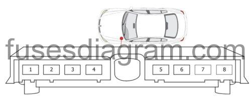
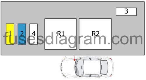
Fuse box in engine compartment.
fuse box diagram (type 1)
| Fuses | Amps | Circuits protected |
|---|---|---|
| 1 | 30A | Hot film air mass sensor Canister purge solenoid Oil level sensor |
| 2 | 30A | Oxygen sensor in front of the catalytic converter Oxygen sensor behind the catalytic converter |
| 3 | 20A | Crankshaft position sensor Camshaft sensor Electronics box (E-box) cooling fan Fuse box in passenger compartment Injectors |
| 4 | 30A | Evaporative canister purge solenoid(s) Engine control unit (DME) |
| 5 | 30A | Power save relay Terminal 15 |
| R1 | DME relay | |
| R2 | Power save relay Terminal 15 |
fuse box diagram (type 2)
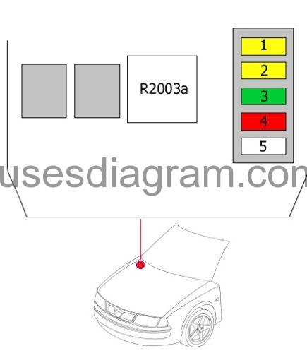
| Fuses | Amps | Circuits protected |
|---|---|---|
| 1 | 20A | Boost pressure sensor Hall sensor Rail pressure control valve Evaporative canister purge solenoid(s), volume control |
| 2 | 20A | Oxygen sensor in front of the catalytic converter Crankcase breather EGR cooler change-over valve Swirl control solenoid Preheating control unit Oil level sensor |
| 3 | 30A | Engine control unit |
| 4 | 10A | Electronics box (E-box) cooling fan |
| 5 | Not used | |
| R2003a | DDE main relay |
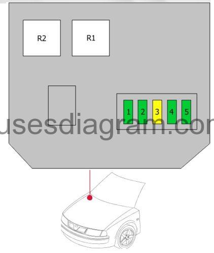
fuse box diagram (type 3).
| Fuses | Amps | Circuits protected |
|---|---|---|
| 1 | 20A | Boost pressure regulator solenoid Camshaft sensor Rail pressure control valve Fuel delivery control solenoid Throttle position valve |
| 2 | 20A | EGR Exhaust gas cooler solenoid Mass airflow meter Oxygen sensor Oil quality sensor Preheating unit |
| 3 | 30A | Engine control unit |
| 4 | 10A | Electronics box (E-box) cooling fan Crankcase breather heater Radiator |
| 5 | Not used |
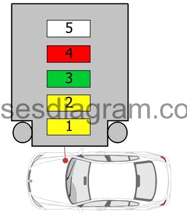
fuse box diagram (type 4).
Fuse 1 (20.0 A) – Engine control unit
Fuse 2 (15.0 A) – Engine control unit
Fuse 3 (50.0 A) – Coolant pump
Fuse 4 (40.0 A) – Valvetronic relay
Relay R1 – Valvetronic relay
Relay R2 – Ignition relay
fuse box diagram (type 5).
| Fuses | Amps | Circuits protected |
|---|---|---|
| 1 | 30A | Ignition coils 1 – 6 |
| 2 | 30A | Coolant pump MAP-controlled engine cooling thermostat Evaporative canister purge solenoid(s) Camshaft sensor |
| 3 | 20A | Canister purge solenoid Engine control unit (DME) Mass airflow meter Oil level sensor Crankshaft position sensor |
| 4 | 30A | Oxygen sensor in front of the catalytic converter Oxygen sensor 2 in front of the catalytic converter Oxygen sensor behind the catalytic converter Oxygen sensor 2 behind the catalytic converter Crankcase breather |
| 5 | 30A | Injectors |
| 6 | 10A | Exhaust manifold flap Electronics box (E-box) cooling fan Fuel tank leak diagnosis Hot film air mass sensor |
| 7 | 40A | Variable valve timing relay |
| 9 | 30A | Coolant pump |
| 10 | 5A | Coolant heater relay |
| R1 | DME relay | |
| R2 | Injectors | |
| R3 | Variable valve timing relay |

